
The hydraulic cylinder is the actuator of a hydraulic system, and its design reliability directly determines the performance and service life of the entire system. This article delves into the core principles of hydraulic cylinder design, starting with its key components to provide an in-depth analysis of critical aspects such as the design essentials, selection criteria, and crucial manufacturing tolerance control of its sealing and guidance systems.
1. Working Principle and Core Components
A hydraulic cylinder is essentially a device that converts hydraulic energy into linear mechanical energy. Its main components include:
- Cylinder Barrel: The core pressure vessel, a hollow steel tube with a highly finished internal surface.
- Piston and Piston Rod: The power transmission components that perform reciprocating motion under the action of pressurized oil.
- End Caps (Head and Cap): Seal the barrel and provide guidance and mounting interfaces.
- Sealing System: The “lifeline” of the cylinder, responsible for preventing internal and external leakage.
- Guidance System: Ensures the concentricity of moving parts, withstands radial loads, and prevents metal-to-metal contact.
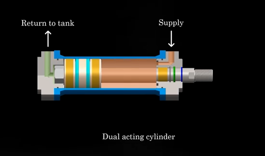
Based on the actuation method, cylinders are classified as Single-Acting (extended by pressure, retracted by an external force or gravity) or Double-Acting (both extension and retraction are controlled by oil pressure). This fundamental difference directly influences the selection of piston seals.
2. The Hydraulic Sealing System: Function, Selection, and Arrangement
Seals are categorized as “Dynamic” (between parts with relative motion) and “Static” (between fixed parts).
2.1 Key Dynamic Seals Explained:
- Piston Seal: The critical dynamic seal preventing internal leakage across the piston.
- U-Cup Seal: A single-acting seal; pressure causes the lip to expand and contact the mating surfaces. Double-acting cylinders require two U-cups installed back-to-back.
- Double-Acting Seal (Compound Seal): Typically consists of an elastomer energizer and a slide ring (e.g., PTFE). PTFE offers a very low friction coefficient and long service life, suitable for high-speed and high-pressure applications. High-end versions integrate anti-extrusion rings to withstand extreme pressures (e.g., 690 bar).
- O-Ring with Backup Rings: Only suitable for low-pressure applications (<100 bar). Backup rings are essential to prevent the soft seal material from being forced into the component gap under high pressure—a phenomenon known as “extrusion failure.”
- Rod Seal: The primary system seal, located in the front end cap, which prevents pressurized oil from leaking to the atmosphere. Typically a single-acting seal like a U-cup.
- Buffer Seal: Positioned before the rod seal, its purpose is not to provide a perfect seal but to dampen pressure spikes, thereby protecting the main rod seal and extending its life. It is usually made of a softer material than the main seal.
- Wiper Seal (Scraper): The first line of defense, located at the outermost side of the end cap. It scrapes contaminants off the piston rod as it retracts, protecting all internal components.
2.2 Static Seals: Used between fixed connections (e.g., piston rod to piston, end cap to barrel), typically O-rings.
2.3 Guide Rings: Their function is guidance, not sealing. Made from low-friction, wear-resistant materials (e.g., polyamide, PTFE), they bear radial loads and prevent direct metal-to-metal contact. Pistons often use guide rings at both ends for optimal stability.
3. Critical Design Parameter: Extrusion Gap and Tolerance Analysis
This is the essence of cylinder design and directly determines seal life.
- Extrusion Gap (E-Gap): The maximum allowable radial clearance between the piston and the cylinder bore (or between the piston rod and the end cap). An excessive gap can cause the seal lip to be extruded into the gap under high pressure, leading to permanent failure.
- Maximum Allowable E-Gap: This value depends on the seal material, hardness, working pressure, and temperature, and must be obtained from the seal manufacturer’s data sheet. For example, a specific seal may allow a 0.6 mm gap at 100 bar, but only 0.2 mm at 350 bar.
- Tolerance Analysis in Practice:
- Define component tolerances: e.g., cylinder bore is often H7, piston rod is often f8.
- Consider the worst-case scenario (Least Material Condition – LMC): This is when the piston is at its smallest diameter and the cylinder bore is at its largest.
- Back-calculate design dimensions: To ensure the maximum possible gap does not exceed the E-gap, the minimum allowable piston diameter must be calculated based on the maximum possible bore size. The manufacturing tolerances for the piston are then defined accordingly.
4. Manufacturing and Surface Treatment Requirements
- Cylinder Bore: Surface finish must be Rz 0.4 – 2 μm, typically achieved by honing or roller burnishing.
- Piston Rod: Surface finish must be Ra 0.4 – 2 μm. It must be case-hardened (Hardness ≥ 50 HRC, depth 1.2-2.5 mm) and hard chrome plated (20-30 μm) to ensure wear and corrosion resistance.
5. Design Example and Arrangement Logic
Using a double-acting cylinder with 20-ton capacity and 100 bar working pressure (Bore: 180mm, Rod: 80mm) as an example:
- Piston Seal Selection: Cost-effective and readily available U-cup seals, installed back-to-back.
- Piston Guidance: Dedicated piston guide rings are placed at both ends of the piston, with the seals in between. This arrangement provides optimal guiding stability and ensures the guide rings are always lubricated.
- Rod End Arrangement (from outside to inside):
- Wiper Seal
- Rod Seal
- Buffer Seal (not strictly necessary in this example, shown for demonstration)
- Rod Guide Ring
Conclusion
Successful hydraulic cylinder design is a systematic engineering process that must adhere to the following core logic:
- Define Operating Conditions: Determine pressure, speed, load, environment, etc.
- Precise Component Selection: Choose the appropriate sealing and guidance solutions based on the conditions. Consulting catalogs and application guides from major manufacturers (e.g., SKF, Parker) is highly recommended.
- Precise Calculation: Perform rigorous tolerance analysis to ensure the “extrusion gap” meets requirements under all manufacturing variations.
- Strict Manufacturing Control: Specify and ensure surface treatment and hardness requirements for critical components.
By systematically applying these principles, one can design hydraulic cylinders that are efficient, reliable, and long-lasting.
Post time: Oct-09-2025