
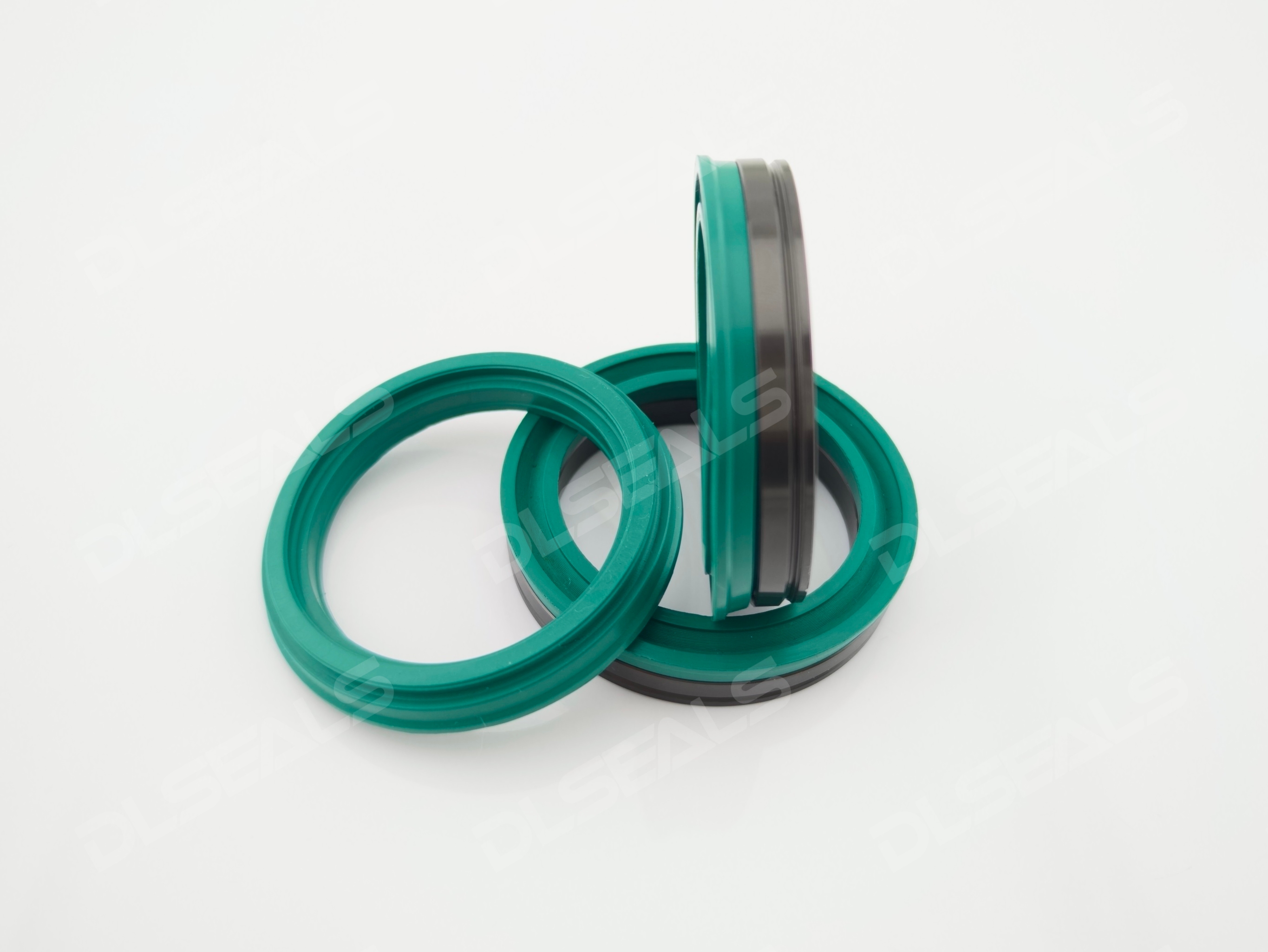
In fluid power and control technology, pneumatic and hydraulic systems are the two core pillars for achieving linear reciprocating motion. As critical components for preventing medium leakage and maintaining system pressure, pneumatic seals and hydraulic seals share commonalities but exhibit significant differences in material selection, structural design, and lubrication mechanisms due to the inherent differences in their working media, operating pressures, and environments.
This article provides a deep technical analysis of the similarities and differences between these two types of seals.
I. Core Similarities: Structural Layout and Sealing Logic
Despite facing different media, pneumatic and hydraulic seals share a high degree of similarity in basic sealing logic and structural classification.
-
Consistency in Structural Layout: Both cylinders share basically the same internal dynamic and static sealing layouts, which mainly include:
-
Piston Seals: Double-acting or single-acting pressure seals used to isolate two chambers and ensure piston thrust.
-
Rod Seals: Single-acting seals that prevent the working medium from leaking into the external environment.
-
Wiper/Dust Seals: Exclude external dust, moisture, and contaminants from entering the system, protecting the primary seals and wear rings.
-
Wear Rings/Guide Rings: Bear radial side loads, prevent direct metal-to-metal contact between the piston/rod and the cylinder body, and ensure concentricity.
-
-
Self-Energizing Sealing Mechanism: Lip seals (such as U-rings and Y-rings) in both systems utilize the self-energizing sealing principle. In an unpressurized state, they rely on the initial interference (pre-compression) of the lip to generate a small initial contact stress. When the system pressure rises, the medium pressure acts on the lip cavity, forcing the lip tighter against the sealing surface, causing the contact stress to increase linearly with the pressure.
II. Core Differences: Mechanical and Physical Environments
The fundamental difference between pneumatic and hydraulic seals stems from the physical properties of their media: gas (compressible, low viscosity, non-lubricating) versus hydraulic oil (incompressible, high viscosity, inherently lubricating).
1. Operating Pressure and Pressure-Resistant Structure
-
Pneumatic Seals (Low-Pressure Systems): Pneumatic systems typically operate between 0.4 to 1.0 MPa. Therefore, pneumatic seals feature thin cross-sections with flexible and sharp lips to achieve minimal frictional resistance.
-
Hydraulic Seals (Medium to High-Pressure Systems): Hydraulic systems operate at pressures from 7 to 35 MPa or even higher (exceeding 70 MPa in ultra-high pressure applications). To prevent the seal from undergoing “material extrusion” under high pressure, hydraulic seals have a thicker cross-section, higher root stiffness, and are often equipped with anti-extrusion backup rings.
2. Lubrication Conditions and Friction/Wear
-
Hydraulic Cylinders: Natural “Abundant Lubrication” The working medium (hydraulic oil) itself is an excellent lubricant. As the hydraulic seal reciprocates, a micron-level oil film forms between the seal lip and the metal surface. The core design focus is to strike a balance between “controlling leakage” and “maintaining oil film lubrication.”
-
Pneumatic Cylinders: Harsh “Lean or Oil-Free Lubrication” Compressed air lacks lubricating properties and easily washes away pre-applied grease. Therefore, pneumatic seals must possess an extremely low coefficient of friction (low breakout friction). They often incorporate self-lubricating components within the material or utilize special aerodynamic lip geometries to prevent “stick-slip” (crawling) phenomena.
3. Material Formulation and Modification
Mainstream materials differ significantly to accommodate their respective pressure and lubrication environments:
-
Pneumatic Seals: Commonly made of NBR (Nitrile Rubber), Polyurethane (PU), or FKM (Fluoroelastomer). PU hardness is usually softer (Shore A 75–85) for low friction and high resilience. Solid lubricants like PTFE or Molybdenum Disulfide are often compounded into the material.
-
Hydraulic Seals: Commonly made of high-density Polyurethane (CPU/TPU), PTFE + Bronze (Slipper seals/Glyd rings), or NBR. PU hardness is much higher (Shore A 90–95 or Shore D 57) for tear and extrusion resistance. The material formulation prioritizes hydrolysis resistance, extrusion resistance, high-temperature resistance, and compatibility with various mineral oils.
4. Speed and Resistance Balance
-
Pneumatic: High frequency and high speed (up to 1 to 2 m/s). Seals must be lightweight with low starting resistance and fast dynamic response.
-
Hydraulic: Low speed and heavy loads (typically < 0.5 m/s). Seals emphasize the ability to maintain “zero leakage” under high static pressure or micro-movements.
III. Technical Comparison Summary
| Technical Indicator | Pneumatic Seals | Hydraulic Seals |
| Typical Pressure Range | ≤1.6 MPa | 10 MPa ~ 70 MPa |
| Working Medium | Compressed air, inert gas | Mineral-based hydraulic oil, synthetic oil, water-based fluids |
| Primary Failure Modes | Wear, dry friction cracking, permanent deformation | Root extrusion damage, lip tearing, thermal aging |
| Cross-Section Design | Thin, long lips, low pre-load | Thick, short lips, high pre-load, often with backup rings |
| Wiper Design Focus | Excludes fine dust, retains internal grease | Forcefully scrapes heavy mud/ice, prevents external ingress |
| Guide Element Material | Engineering plastics like POM, PA | Phenolic fabric, PTFE with wear-resistant fillers |
IV. Conclusion and Engineering Recommendations
In short, pneumatic seals excel at “responsiveness and low friction,” while hydraulic seals master “high pressure and heavy load.”
In practical engineering and maintenance, the principle of “dedicated parts for dedicated applications” must be strictly followed:
-
Never use pneumatic seals in hydraulic systems: The thin structures and softer materials will instantly extrude and tear under high hydraulic pressure, causing catastrophic system failure.
-
Avoid using standard hydraulic seals in pneumatic systems: High pre-load and high-hardness hydraulic seals will cause excessive starting resistance and severe dry friction wear due to lack of lubrication, drastically shortening service life.
Post time: Jul-07-2026


