
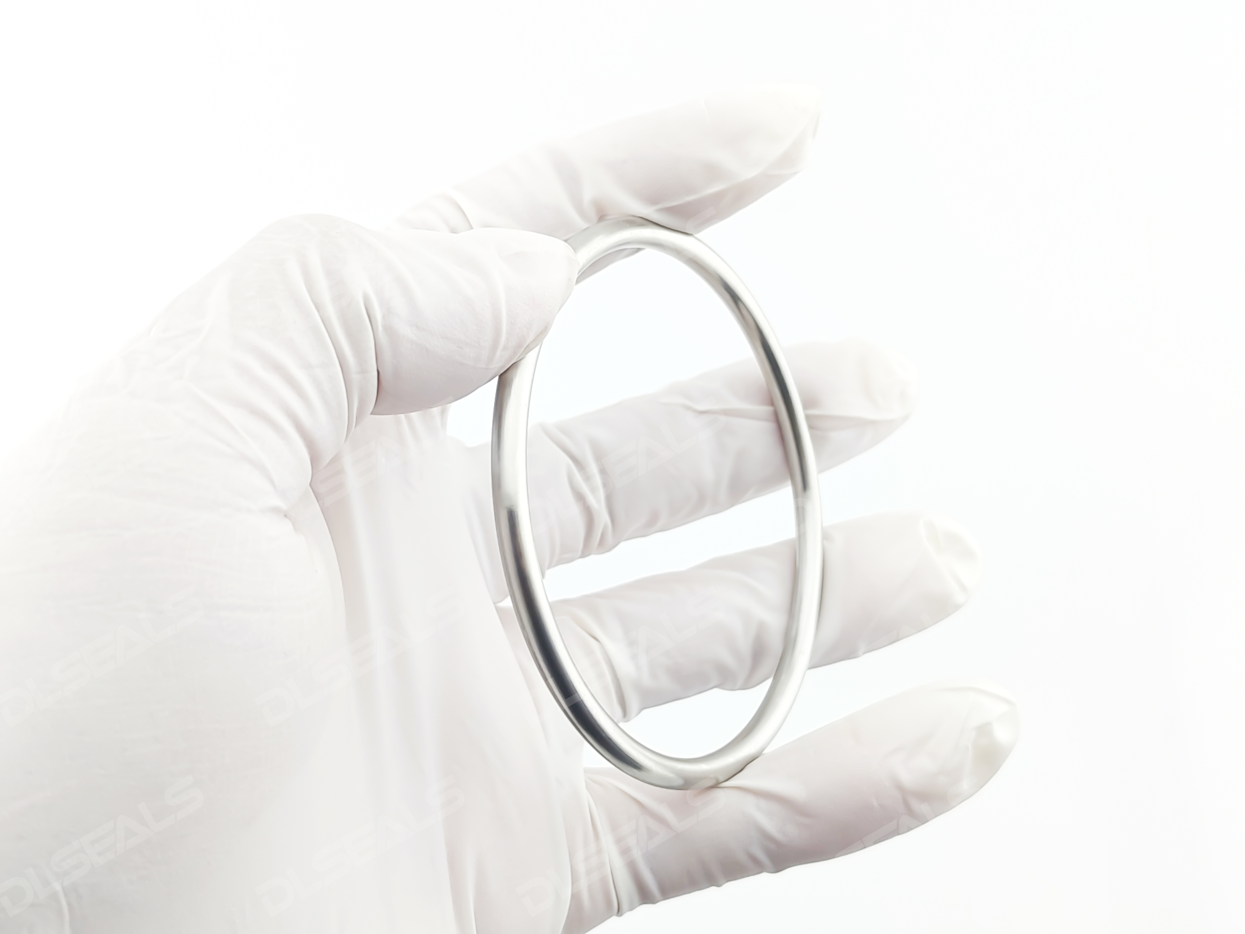
The metal hollow O-ring is a circular sealing ring made from metal tubing, typically with a circular cross-section (though oval, rectangular, etc., are also possible). It functions by deforming elastically under compression to fill the micro-gaps between sealing interfaces, thereby achieving a seal. Unlike elastomeric seals, it is specifically designed to address sealing challenges in extreme environments involving high temperature, high pressure, high vacuum, and strong corrosion.
I. Working Principle: Elastic Deformation and Line Contact Sealing
The sealing principle of the metal hollow O-ring is based on the classic “line contact” mechanism, which involves the following key steps:
- Preload and Line Contact:
- When flanges or connectors are tightened with bolts, the groove cover applies an axial compression force to the metal hollow O-ring.
- This force causes the wall of the hollow metal ring to undergo elastic deformation (flattening), pressing its outer wall tightly against the bottom of the sealing groove and the cover plate, forming a continuous “line contact” sealing band. This initial contact provides the basic static seal.
- System Pressure-Assisted Sealing (Self-Energizing Effect):
- When the internal system pressure increases, the medium pressure acts on the inside of the O-ring, either through vent holes in the groove base or directly.
- The pressure further forces the O-ring to expand outward, pressing its sealing lip (the contact edge formed by flattening) more tightly against the opposing sealing surface. The higher the system pressure, the greater the sealing contact pressure. This “self-energizing effect” significantly enhances sealing reliability.
Difference from Solid Metal O-Rings:
- Solid metal O-rings primarily rely on large compression forces to plastically deform the metal to fill gaps. They require high sealing forces and are often not reusable after disassembly.
- Hollow metal O-rings primarily rely on the elastic deformation of the tube wall, requiring much lower sealing forces and offering better elastic recovery, resulting in superior reusability.
II. Core Advantages
Based on its working principle and metal material, metal hollow O-rings offer the following outstanding advantages:
- Extremely Wide Temperature Tolerance: Its most notable advantage. Depending on material choice (e.g., Inconel, stainless steel 316, Hastelloy), it can withstand extreme temperatures from -250°C to over 1000°C, far exceeding any polymer sealing material.
- Excellent High-Pressure and High-Vacuum Sealing Performance: Capable of withstanding ultra-high pressures of hundreds of Megapascals (MPa). In high-vacuum systems, the very low gas permeability of the metal itself ensures excellent vacuum integrity.
- Outstanding Corrosion Resistance: Special alloys can resist various strong acids, alkalis, organic solvents, and high-temperature oxidation environments.
- No Creep or Relaxation, Long-Lasting Seal: Metal materials do not creep or age like plastics or rubbers at high temperatures, maintaining a stable sealing force long-term and preventing leakage due to relaxation.
- Reusability: With correct design and installation, as long as permanent crushing (over-compression) does not occur, it can be disassembled and reused multiple times, reducing long-term maintenance costs.
- Radiation Resistance: Suitable for environments with radiation exposure, such as the nuclear industry.
III. Installation Groove Design and Key Parameters
Groove design is critical for the proper functioning of metal hollow O-rings. The core objective is: to provide precise compression space for the O-ring while restricting its lateral flow.
1. Groove Types
- Open Groove (Most Common): The groove is machined into one flange face, and the other is a flat sealing surface. Suitable for most high-pressure static seals.
- Closed Groove (Two-part Groove): The groove is formed by machining a half-groove into each flange face. Facilitates O-ring positioning and installation but requires high machining accuracy.
2. Key Groove Dimension Design
Groove dimensions are closely related to the O-ring’s free diameter (OD) and wall thickness (WT). The following are basic design principles for circular cross-section hollow metal O-rings (specific dimensions should refer to standards or supplier recommendations):
- Groove Width (W):
- Should be slightly larger than the O-ring’s free diameter (OD) to accommodate it. Typically, W ≈ OD + (10% ~ 20%) OD.
- The width must not be excessive, otherwise, the O-ring may deform excessively under pressure and be extruded into the gap, causing damage.
- Groove Depth (D):
- This is the most critical parameter, directly determining the O-ring’s compression ratio.
- Compression Ratio = (OD – D) / OD × 100%
- For static seals, the recommended initial compression ratio is typically between 15% and 30%. Too low a ratio can cause leakage; too high can crush the O-ring, causing loss of elasticity and making it non-reusable.
- Groove depth (D) must be less than the O-ring’s free diameter (OD).
- Groove Surface Roughness:
- The surface roughness of the sealing contact faces is crucial. Typically, Ra ≤ 0.8 μm is required to ensure good line contact and minimize leakage paths.
- Groove Corners:
- The junction between the groove bottom and sidewall should have a suitable radius (small chamfer) to prevent stress concentration and scoring of the O-ring.
3. Compression Control: Percent Compression
After installation, the height of the O-ring is compressed. This degree of compression is measured by “percent compression”.
- Percent Compression = (Free Height – Compressed Height) / Free Height × 100%
- For standard circular cross-section hollow metal O-rings, 20% – 30% compression is a common and effective range. This must be ensured by precisely calculating the groove depth and selecting appropriate gaskets or spacers.
IV. Typical Applications
- Aerospace: Engines, fuel systems, high-temperature pipelines.
- Petrochemicals: High-temperature, high-pressure reactors, valves, pipe connections.
- Nuclear Industry: Nuclear reactors and related equipment.
- Vacuum Furnaces, Semiconductor Equipment: Chamber door seals requiring ultra-high vacuum maintenance.
- Supercritical Fluid Equipment.
Conclusion
The metal hollow O-ring is one of the ultimate solutions for sealing challenges in extreme conditions. Its successful application depends heavily on correct material selection (matching the medium and temperature), precise groove design (controlling compression), and clean, professional installation. When selecting and using them, it is highly recommended to consult in detail with professional suppliers or standard specifications (such as the AMS series) to ensure fail-safe operation.
Post time: Oct-20-2025