
Metal sealing rings (also known as metal seals or metal O-rings) are non-elastomeric sealing elements designed for extreme conditions, including high temperatures (up to 980°C), high pressures (up to 1400 kgf/cm²), ultra-high vacuum (10⁻⁹ torr), strong corrosion, radiation, or nuclear environments. Unlike rubber O-rings, they achieve near-zero leakage through elastic-plastic deformation of the metal tube, pressure self-energizing, or coating filling. They do not age, do not permeate, and offer extremely long service life. Common types include hollow metal O-rings (standard / pressure-balanced / gas-pressurized), C-rings, E-rings, ring joint gaskets (R-type / oval), etc. The selection follows six steps: operating conditions → type → material & coating → dimensions → groove design → validation. It is recommended to refer to international vacuum flange standards or general engineering guidelines.
Step 1: Operating Conditions Analysis (Requirement Gathering)
Define the key parameters — this is the foundation of selection:
Sealing type: Almost always static (flanges, valves, pressure vessels, aerospace engines); rarely dynamic.
Medium: Gases, liquids, strong acids/alkalis, radioactive substances, vacuum.
Temperature range: Cryogenic (-270°C) to high temperature (980°C), including thermal cycling.
Pressure: Vacuum to 680 MPa (with pulsation requires pressure-balanced type); high pressure benefits from self-energizing effect.
Other: Leakage rate requirement (<10⁻⁹ Pa·m³/s), radiation resistance, corrosion resistance, installation space, bake-out temperature, cost.
Tips: For high-temperature/high-pressure cycling, prefer gas-pressurized type; for ultra-high vacuum knife-edge flanges, prioritize oxygen-free copper or aluminum rings; food/nuclear applications require special certifications.
(Images would typically show compression deformation principle: original circular cross-section → compressed elastic recovery filling gaps, providing sealing force.)
Step 2: Type Selection
Match type to pressure/temperature (key difference from elastomeric seals):
Hollow metal O-rings:
Standard type: Medium/low pressure/vacuum (≤70 kg/cm²), simple structure.
Pressure-balanced (self-energizing): High pressure (>70 kg/cm²), small holes in inner wall introduce system pressure — higher pressure increases sealing force.
Gas-pressurized (internally pressurized): High-temperature cycling (425–980°C), internal gas expands with temperature to enhance sealing.
C-rings: Open side faces pressure, plastic recovery + self-energizing, suitable for flange connections with low bolt preload.
E-rings / K-rings: Higher resilience, good for large diameters or eccentric applications.
Ring joint gaskets: R-type / oval, for oil & gas pipeline flanges, solid metal extrusion sealing.
Selection principle: Low pressure/vacuum → standard O-ring; high pressure → pressure-balanced O-ring or C-ring; high-temperature cycling → gas-pressurized O-ring. Prefer larger tube cross-section diameter (higher sealing load, better tolerance accommodation).
Step 3: Material and Coating Selection
Material determines temperature/corrosion resistance; coating improves initial sealing:
Tube body materials:
Stainless steel 304: -250 to 540°C, general corrosion resistance.
Stainless steel 321: -250 to 870°C, high-temperature stability.
Inconel 718 / Alloy X750 equivalents: -270 to 980°C, highest strength/radiation resistance.
Coatings / surface treatments (thickness 0.03–0.12 mm):
Silver: -250 to 650°C, best sealing performance.
PTFE: -250 to 260°C, low friction.
Gold, nickel, copper, indium: Match to medium/temperature.
Solid metal gaskets: Oxygen-free copper (for knife-edge flanges), pure aluminum, indium wire.
Selection principle: Check compatibility tables for medium corrosion and temperature; high temperature prefers high-nickel alloys with silver coating; cryogenic/ultra-vacuum prefers aluminum/indium. Keep material in soft/annealed state for good deformation.
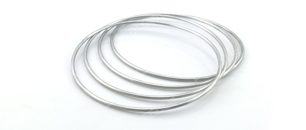
(Images would typically show typical metal sealing rings in different materials and coatings, with visible appearance differences.)
Step 4: Dimension Selection (Tube Outer Diameter + Wall Thickness + Ring Diameter)
Standards/custom: No universal global standard like AS568; dimensions are series-based (tube OD 0.9–6.4 mm, ring OD 10–1500+ mm).
Key parameters:
Tube outer diameter (cross-section): 0.9 / 1.6 / 2.4 / 3.2 / 4.0 / 4.8 / 6.4 mm (larger = higher sealing force).
Wall thickness: 0.15–0.80 mm (thinner = better resilience; thicker = better high-pressure resistance).
Ring diameter: Matched to flange bore; control radial/axial stretch/compression within 5%.
Pressure-balanced type: Hole position on inner/outer diameter must align with pressure direction.
Calculation notes: Sealing load depends on wall thickness, tube diameter, coating; high pressure prefers thick wall + pressure-balanced; large diameter (>250 mm) limits stretch to ≤3%.
Step 5: Groove Design (Core Technical Step)
Grooves are typically rectangular, knife-edge, or stepped to ensure proper compression and contact pressure:
Compression rate: 10–30% (standard 15–20%, pressure-balanced 25–30%); formula: Compression = (free height – groove depth) / free height.
Groove depth: Tube OD × (1 – compression rate), with 0.05–0.1 mm allowance.
Groove width: 1.1–1.3 × tube OD (accommodates deformation + coating).
Other requirements:
Surface roughness: Mating faces Ra ≤ 0.8 μm, groove Ra ≤ 1.6 μm.
Fillets/chamfers: R 0.2–0.5 mm, 15–20° chamfer to prevent damage.
High pressure/vacuum: Add locating outer ring or knife-edge; pressure direction determines opening orientation (C-ring self-energizing).
Volume fill: 70–85% (similar to elastomers but with minimal metal deformation).
Common groove types:
Flat flanges: Rectangular groove + outer locating ring.
Knife-edge flanges: Oxygen-free copper ring directly compresses edge.
Ring joint: Trapezoidal groove (R-type gasket specific).
High pressure requires eccentricity compensation; groove tolerances H8/f8 class.
(Images would typically show typical ring joint gasket dimensions and groove/oval structure for high-pressure pipeline flanges.)
Step 6: Installation, Validation, and Optimization
Installation notes: Clean surfaces with acetone (oil-free), insert vertically (misalignment <0.2 mm), apply gradual pressure (step-torque bolts), use compatible lubricant, avoid twisting/scratches. Knife-edge flanges require precise alignment.
Validation: Helium mass spectrometer leak test (<10⁻⁹ Pa·m³/s), pressure cycling test (72+ h + high-temperature bake-out), life simulation. Optimize by adjusting wall thickness/coating.
Common issues to avoid: Over-compression (permanent set), rough surfaces (leakage), no coating (poor initial seal).
Recommended tools: Use general engineering calculators or handbooks for input of pressure/temperature/dimensions to recommend type, material, and groove.
Final recommendation: Metal sealing rings can achieve 5–10 times longer life than elastomeric seals, but require higher preload and higher cost. Always perform prototype testing (especially for thermal cycling). For specific conditions (medium, pressure, temperature, flange size), precise recommendations can be made.
Refer to reliable engineering guidelines and vacuum/flange standards to ensure zero leakage and safety. For complex conditions, consult professional sealing engineers or perform FEA simulation. In extreme environments, metal sealing rings are the preferred solution!
Post time: Mar-20-2026