
Spring-energized seals, also known as spring-loaded seals or energized PTFE lip seals, are high-performance U-cup style seals consisting of a precision-machined polymer jacket (typically PTFE or other high-performance plastics) with an internal metal spring (cantilever/V-type, helical, canted coil/O-type, or spiral). The spring provides constant initial preload, while system pressure assists in energizing the lips for reliable sealing. This design overcomes limitations of traditional rubber O-rings in extreme conditions: wide temperature range (-200°C to +300°C), pressures over 700 kg/cm², aggressive chemicals, vacuum, or dry-running environments. They feature ultra-low friction (0.05–0.15), negligible aging or swelling, and long life — often 3–10 times that of conventional seals. Ideal for hydraulics, aerospace, semiconductors, medical devices, petrochemicals, compressors, valves, etc. Unlike pure elastomeric deformation in O-rings or plastic extrusion in metal seals, spring-energized seals combine spring preload, pressure self-energizing, and low-friction lips. Selection focuses on operating conditions, spring type, materials, dimensions, and groove design, following general industry engineering practices and standards. The process includes 6 steps; professional calculation tools are recommended for precision.
Step 1: Operating Conditions Analysis (Requirement Gathering)
Define key parameters — the foundation of selection:
- Sealing type: Static, reciprocating (rod/piston), rotary, or combined motion.
- Medium: Oils, water, acids/alkalis, solvents, gases, vacuum, radioactive fluids.
- Temperature range: Cryogenic (-200°C) to high (+300°C), including thermal cycling.
- Pressure: Vacuum to >700 kg/cm² (high pressure requires self-energizing designs).
- Speed: Reciprocating <5 m/s, rotary <20 m/s (dry-running limits stricter).
- Other: Friction requirements, leakage rate (<10⁻⁹ Pa·m³/s), installation space, surface finish (Ra ≤0.2–0.4 μm), radiation/cleanliness.
Tips: Preferred where elastomers fail (high temperature/corrosion, dry running, zero/low-pressure startup, ultra-low temperature); add backup/support rings for high pressure/pulsation or eccentricity.
Step 2: Type and Spring Selection
Match to pressure, motion, and friction needs (key differentiator from other seals):
- Cantilever/V-spring: High pressure (>100 kg/cm²), high resilience, suited for reciprocating dynamic sealing, moderate friction.
- Helical/U-spring (fingered/spiral): Low/zero-pressure startup, rotary sealing, lowest friction, large tolerance accommodation.
- Canted coil/O-spring (round/flat wire): Ultra-low friction, rotary or ultra-clean applications (semiconductor/medical).
- Special variants: Canted, offset lips, double lips, scraper edges, rotary-specific (with cantilever reinforcement).
Selection principle: High-pressure reciprocating → V/cantilever; rotary/low-friction → helical/U or canted coil; extreme corrosion/vacuum → special alloys + filled PTFE. Prefer asymmetric lip designs (shorter/thicker dynamic lip for reduced friction).
(Above image shows typical spring-energized seals: various colors/profiles/materials, including white virgin PTFE, black filled, etc.)
Step 3: Material Selection
- Jacket materials (control chemical/temperature performance):
- Virgin PTFE: -200 to +260°C, broadest media compatibility.
- Filled PTFE (carbon fiber, glass fiber, MoS₂, bronze): Enhanced wear resistance, lower friction, high pressure.
- PEEK/UHMWPE: Higher strength/abrasion resistance (up to +300°C).
- Others (e.g., PCTFE): Ultra-low temperature specialized.
- Spring materials:
- 301/316 stainless steel: General purpose.
- Hastelloy C276, Inconel: Severe corrosion/high temperature.
- Titanium: Lightweight/medical grade.
- Coatings/modifications: Optional MoS₂ or PTFE coatings for further friction reduction.
Selection principle: Check media compatibility charts (PTFE nearly universal except molten alkali metals); high temperature/pressure prefers filled PTFE + corrosion-resistant springs; food/medical requires FDA-compliant grades.
Step 4: Dimension Selection (Cross-Section Diameter + Ring Diameter)
- Standard series: Industry-common sizes (cross-section 2.4–9.5 mm typical), inner/outer diameters custom to shaft/bore; no single universal standard but series tables available.
- Key parameters:
- Cross-section diameter (d2): Larger provides better tolerance compensation and sealing force (start with 3.5–6 mm).
- Lip height/width: Asymmetric for dynamic applications.
- Stretch/compression: Radial installation 2%–5% (rotary <3%).
- Rotary-specific: Grooved or reinforced structures for higher speeds.
Calculation notes: Initial sealing force = spring force + pressure × area; prioritize larger cross-sections for eccentricity/wear compensation.
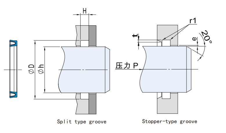
Step 5: Groove Design (Core Technical Step)
Grooves are typically rectangular or stepped, ensuring proper lip compression, spring preload, and back-pressure space:
- Compression rate: 10%–25% (low pressure 10–15%, high pressure 20–25%); formula: Compression = (free height – groove depth) / free height.
- Groove depth: Cross-section diameter × (1 – compression rate), with 0.05–0.1 mm allowance.
- Groove width: 1.05–1.25 × cross-section diameter (accommodates expansion + lip deformation).
- Other requirements:
- Surface finish: Mating Ra ≤0.2 μm, groove Ra ≤0.8 μm.
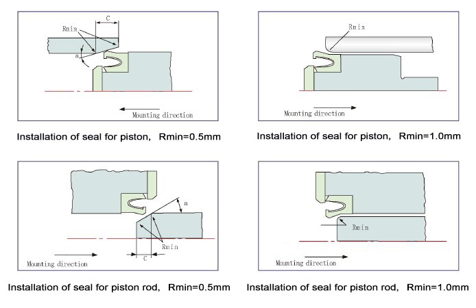
- Chamfers/fillets: 15°–20° lead-in chamfer (prevents lip damage), R 0.2–0.5 mm.
- High pressure (>200 kg/cm²): Add support/backup rings (PEEK or metal) to prevent extrusion.
- Volume fill: 75%–85%.
- Pressure direction: Lips/opening face high-pressure side.
Common groove types:
- Radial piston/rod: Rectangular with lead-in chamfer.
- Rotary: Axial locating features.
- Static face: Shallow grooves.
Step 6: Installation, Validation, and Optimization
- Installation notes: Clean surfaces (no oil/burrs), use compatible lubricant/tools, install vertically (avoid lip inversion), torque bolts stepwise/uniformly, verify spring integrity.
- Validation: Pressure/temperature cycling tests (72+ h), helium leak detection, friction/life simulation. Optimize by adjusting spring type or fillers.
- Common issues to avoid: Insufficient compression (low-pressure leakage), rough surfaces (lip wear), no backup rings (high-pressure extrusion), installation scratches.
Recommended tools: Industry handbooks or online calculators (input conditions to recommend cross-section, groove, tolerances).
Final recommendation: Spring-energized seals are the “universal” choice for extreme conditions where elastomers or metals fail, delivering near-zero leakage and extended life with proper selection. Always prototype test (especially high-speed/high-temperature cycling). Provide specific parameters (medium, pressure, temperature, shaft diameter) for precise groove and model recommendations.
Refer to general engineering standards and sealing handbooks for system safety and reliability. For complex cases, perform FEA simulation or consult professional sealing engineers. In advanced equipment, spring-energized seals have become an indispensable core sealing solution!
Post time: Mar-23-2026