
Valve stem seals (also known as valve stem oil seals or valve guide seals) are precision sealing components essential to the cylinder head assembly of internal combustion engines. Installed between the valve guide and the valve stem, their primary function is to precisely control the thickness of the oil film formed between the valve stem and guide while preventing excessive engine oil from leaking into the combustion chamber. In modern automotive engines—especially high-revving, turbocharged, and direct-injection engines—the reliability of valve stem seals is extremely high. Their performance directly affects oil consumption, emission compliance, carbon deposit formation, and overall engine longevity. This article provides a professional and detailed technical analysis of valve stem seals, covering their working principles, structure, materials, manufacturing processes, installation and maintenance, as well as fault diagnosis.
1. Functions and Working Principles of Valve Stem Seals
During engine operation, the valve stem reciprocates at high speed inside the valve guide (up to tens of thousands of cycles per minute). The valve guide requires continuous lubrication to reduce friction and wear. However, uncontrolled oil leakage into the combustion chamber causes several problems:
- Incomplete combustion, increased carbon deposits, and higher emissions (elevated HC, CO, and particulate matter);
- Abnormally high oil consumption;
- Fouled spark plugs and increased risk of knocking.
The core principle of a valve stem seal is dynamic lip sealing. It uses an elastic lip to form a micron-level oil film on the valve stem surface while the radial force provided by an internal spring creates a “scraper” effect. This allows only a minimal amount of lubricating oil to pass through while blocking large quantities of oil from flowing down the stem into the combustion chamber. In typical designs, the permitted oil film thickness is only 0.5–2 μm, ensuring adequate lubrication with minimal leakage.
In the alternating negative and positive pressures of the intake and exhaust strokes, the seal must also withstand instantaneous pressure differentials (up to several bar) and high temperatures (locally exceeding 200°C). Therefore, its sealing performance must balance low friction, fatigue resistance, and chemical stability.
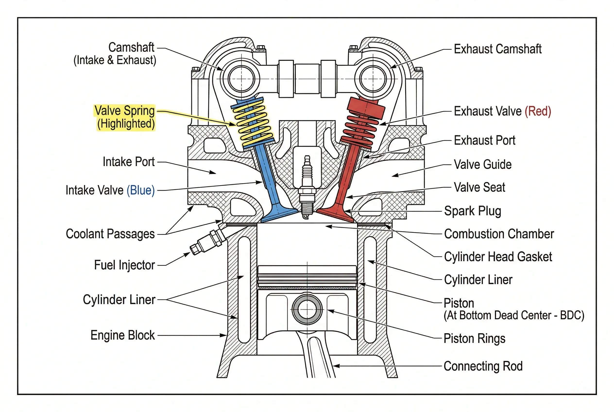
(The above images show a typical engine valve train cross-section with the valve stem seal clearly labeled.)
2. Structural Design and Classification
Modern valve stem seals generally adopt a composite structure consisting of the following key components:
- Rubber/Elastomer Lip: The sealing working surface in direct contact with the valve stem;
- Metal Skeleton (steel plate or stainless steel): Provides structural rigidity and prevents lip deformation;
- Tension Spring (Garter Spring, usually stainless steel coil spring): Maintains constant radial pressure on the lip (typically 0.5–2.5 N);
- Dust Lip / Auxiliary Lip (in some premium models): Prevents external contaminants from entering.
Common classifications include:
- Umbrella/Deflector Seals: Shaped like an inverted umbrella with a longer lip, relying primarily on inherent elasticity for oil scraping. Simple structure and low cost, suitable for medium- to low-speed engines, but prone to aging at high temperatures.
- Positive Seals: Cup-type or O-ring designs with a metal shell and built-in spring, offering more reliable sealing for high-performance engines.
- Hybrid/Combination Types: Combine umbrella and positive lips, or feature low-friction PTFE coatings; commonly used in turbocharged and direct-injection engines.
Different models vary significantly in appearance: black for traditional NBR, blue/red for high-temperature FKM, and those with gold-colored metal rings for premium reinforced types.
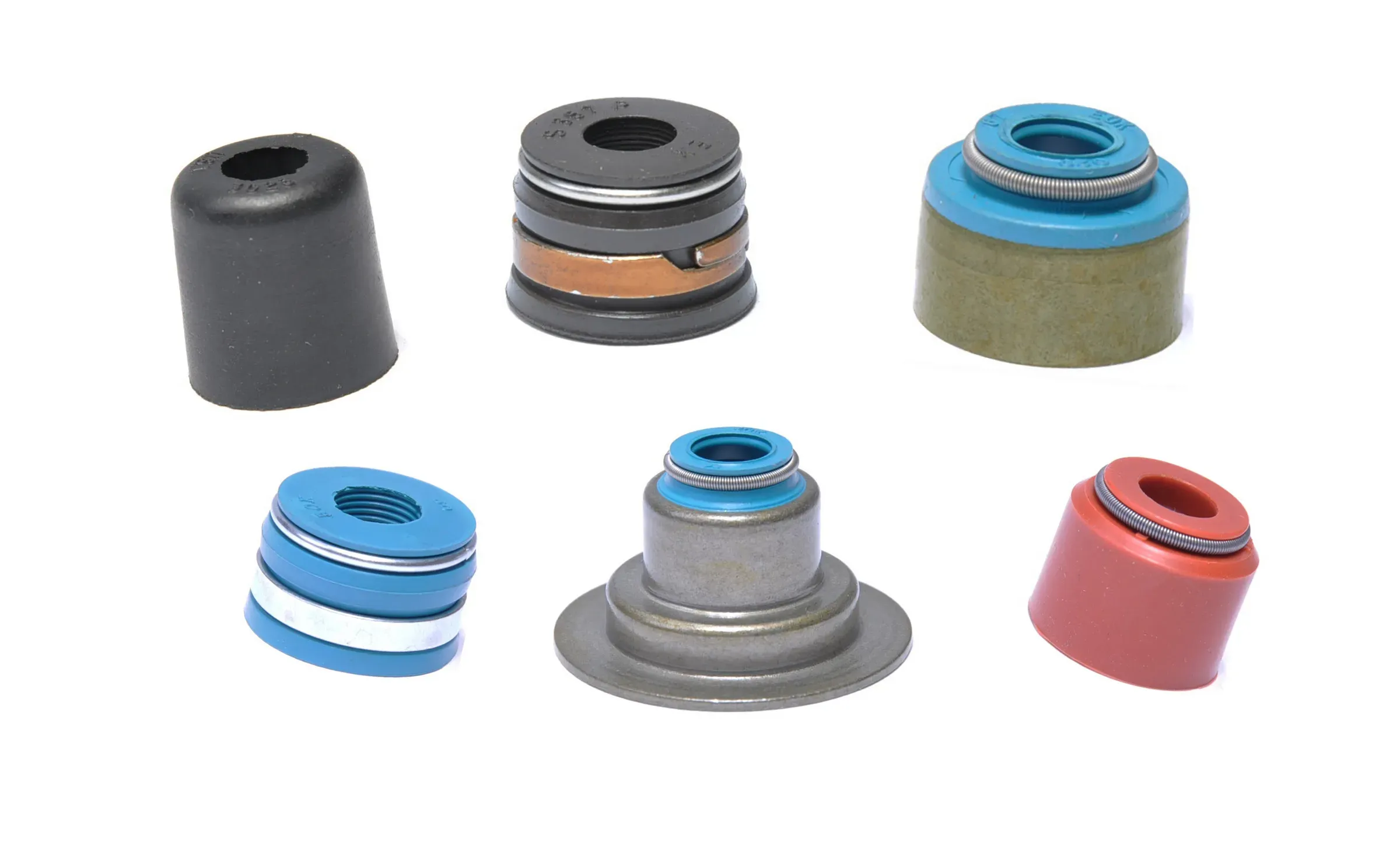
(The above images display various valve stem seals in real form along with structural details, clearly showing stainless steel springs, high-quality FKM lips, and thickened steel plates.)
3. Material Selection and Performance Requirements
Valve stem seals operate in extreme environments: temperature range from -40°C to +200°C (higher instantaneously), exposure to hot engine oil, fuel vapors, and combustion by-products, while enduring reciprocating friction and chemical corrosion. Material selection is therefore the core technology.
- Mainstream Elastomers:
- NBR (Nitrile Butadiene Rubber): Commonly used in early designs; good oil resistance but heat limit around 120°C, prone to hardening and cracking.
- FKM (Fluoroelastomer / Viton): Current mainstream material; heat resistance up to 200°C+, excellent oil and chemical resistance, low compression set. High-fluorine-content FKM is used in premium models.
- ACM (Acrylic Rubber) or AEM (Ethylene Acrylic Rubber): Balance heat resistance and cost, suitable for mid- to high-end passenger vehicles.
- PTFE (Polytetrafluoroethylene) Coating: Applied to the lip surface to significantly reduce the friction coefficient (down to below 0.1), minimizing wear and energy loss.
- Metal Components: SUS304/SUS316 stainless steel springs for fatigue resistance; skeletons made of deep-drawn cold-rolled steel plates with phosphating or zinc plating for corrosion protection.
Typical OEM performance specifications:
- Radial force: 1.0–2.0 N (new part);
- Leakage rate: <0.1 g/h (standard bench test);
- Durability: >2,000 hours of high-temperature reciprocating test with no significant increase in leakage;
- Hardness: Lip Shore A 70–85°.
Material choice directly determines seal service life: FKM-type seals can last over 150,000 km in modern turbocharged engines, while low-end NBR types may fail after only 50,000–80,000 km.
4. Manufacturing Process Overview
Valve stem seal production is a precision rubber-metal composite process:
- Metal skeleton stamping and surface treatment;
- Rubber vulcanization bonding (using specialized adhesives to ensure interface strength >5 MPa);
- Precision mold forming (lip dimensional accuracy ±0.05 mm);
- Spring assembly and post-processing (laser marking, rust-preventive oiling).
Leading manufacturers (such as NOK and Freudenberg) employ fully automated production lines with 100% online radial force inspection and vacuum leak testing to ensure batch consistency.
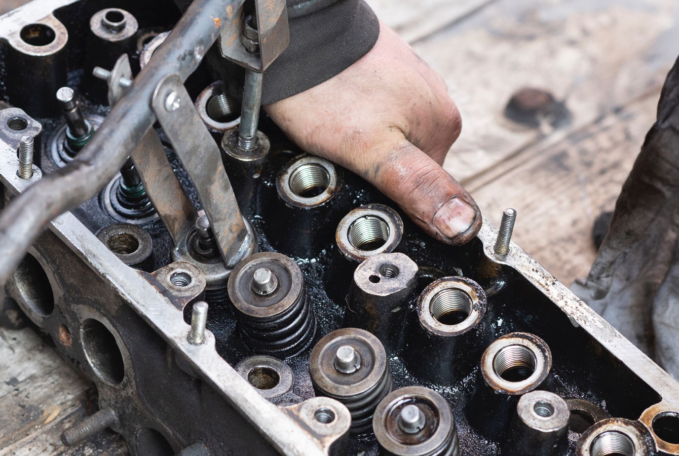
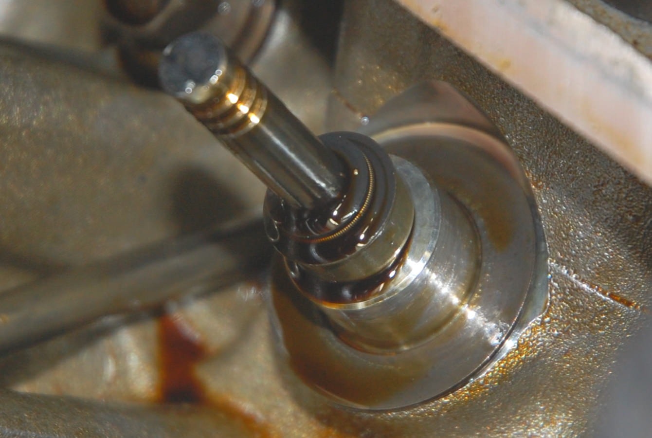
5. Installation, Replacement, and Maintenance
Valve stem seal replacement is a standard procedure during major engine overhauls, usually performed together with valve lapping and guide replacement.
Key Installation Points:
- Use a dedicated valve spring compressor for disassembly and reassembly;
- Employ stepped installation tools (plastic or brass sleeves) to avoid lip rollover or damage;
- Apply a small amount of clean engine oil to the lip before installation;
- The valve stem surface must be smooth and free of burrs (Ra < 0.4 μm);
- After replacement, perform valve clearance adjustment and cylinder pressure testing.
Precautions: Never hammer the seal directly; use a dedicated puller when removing old seals to avoid scratching the guide.
Routine maintenance: Regularly monitor oil consumption (normal <0.5 L/1,000 km) and use OBD data to check for idle vibration or misfire codes. When abnormalities occur, inspect the valve stem seals first rather than replacing piston rings alone.
6. Common Fault Diagnosis and Troubleshooting
Typical fault symptoms:
- Blue/white thick smoke: Especially noticeable on cold starts (due to aged seals allowing oil to seep down);
- Abnormal oil consumption (>1 L/5,000 km);
- Heavy carbon deposits on spark plugs and reduced power.
Diagnostic procedure:
- Rule out other oil leak sources such as PCV valve or turbo seals;
- Perform cylinder pressure and leak-down tests;
- Disassemble the cylinder head and visually inspect the seal lips for hardening, cracking, or looseness.
Resolution: Replace all seals with the same specification FKM type. It is recommended to replace the complete valve guide seal kit at the same time.

(The above image shows the typical blue exhaust smoke caused by failed valve stem seals.)
7. Technology Trends and Innovations
With increasingly stringent emissions regulations (China VI/Euro 7) and the trend toward electrification, valve stem seals are evolving in the following directions:
- Low-friction nano-coatings: Further reduce fuel consumption by 0.5%–1%;
- Integrated modules: Formed as one piece with the valve guide to minimize assembly errors;
- Smart monitoring: Some high-end engines are experimenting with embedded sensors to monitor lip pressure;
- Bio-based/environmental materials: To meet carbon-neutrality requirements.
In the high-performance aftermarket (e.g., racing engines), specially formulated high-strength FKM with multi-layer springs is used to handle speeds above 8,000 rpm.
Conclusion
Although small in size, valve stem seals are the “invisible guardians” of efficient, clean, and reliable operation in internal combustion engines. Every advancement in their materials, structure, and manufacturing processes directly drives engines toward higher thermal efficiency and lower emissions. For engine repair technicians and R&D engineers, a deep understanding of valve stem seal technical details is key to ensuring engine performance and longevity. In practical applications, it is strongly recommended to use OEM or reputable brand FKM-material products and perform preventive replacement according to the manufacturer’s mileage/time guidelines to achieve optimal economy and reliability.
Further optimization for specific engine models can be achieved by referring to professional service manuals and OEM technical specifications. This article aims to provide automotive engineering professionals with a systematic technical reference.
Post time: Apr-15-2026


