
The crankshaft rear oil seal is a critical component in the engine sealing system. Its performance directly affects the engine’s reliability, emission levels, and service life. This article aims to comprehensively analyze the core functions, material science, key technical requirements, failure modes, and installation specifications of the crankshaft rear oil seal, providing systematic technical reference for relevant engineering and technical personnel.
1. Core Functions and Operating Environment
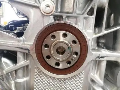
The crankshaft rear oil seal is installed at the power output end of the engine crankshaft, i.e., the junction with the transmission. It primarily performs two core functions:
- Static Sealing: When the engine is stationary, it forms a physical barrier through the interference fit between the sealing lip and the crankshaft flange or journal surface, preventing oil leakage from the crankcase.
- Dynamic Sealing: It continuously and effectively maintains the seal while the crankshaft rotates at high speed (up to 6000+ rpm) with radial runout (typically 0.2-0.8mm) and slight axial movement.
Its operating environment is extremely harsh:
- Temperature: Constantly exposed to hot engine oil at 100-150°C, with short-term tolerance for even higher temperatures.
- Medium: In contact with modern engine oil containing various additives (detergents, dispersants, anti-wear agents, etc.).
- Operating Conditions: Subjected to alternating loads, vibrations, and must adapt to various states from extreme cold starts to high-temperature full load.
2. Material Science and Structural Design
1. Main Material Selection
Material is the foundation determining seal performance, requiring high-temperature resistance, oil resistance, wear resistance, and high elasticity.
- Primary Sealing Material:
- Fluoroelastomer (FKM/Viton): Most widely used. Excellent resistance to fuel and oil at high temperatures with low compression set, suitable for high-performance gasoline and diesel engines.
- Acrylate Rubber (ACM/AEM): Cost-effective with good hot oil resistance, but slightly inferior low-temperature performance, commonly used in medium-to-low load engines.
- Hydrogenated Nitrile Butadiene Rubber (HNBR): Combines good oil resistance, wear resistance, and excellent low-temperature elasticity, suitable for wide temperature range applications.
- Polytetrafluoroethylene (PTFE): Extremely low friction coefficient and excellent chemical resistance, often used for composite lips or special applications.
- Reinforcing Skeleton: Typically made from stamped low-carbon steel sheet, surface-treated with phosphating or galvanizing for rust prevention, providing structural strength and installation interference force.
- Garter Spring: Usually a stainless steel coil spring that continuously provides radial pressure to the sealing lip, compensating for lip wear and ensuring long-term sealing.
2. Key Structural Design
Modern crankshaft rear oil seals use composite structures to enhance performance:
- Hydrodynamic Return Ribs: Precise spiral, wave, or diagonal grooves are machined on the air side of the sealing lip contact area. When the crankshaft rotates, a minute amount of oil penetrating the lip is “pumped” back into the engine by these grooves, achieving active sealing.
- Primary/Secondary Lip and Dust Lip: The primary lip performs the core sealing; the secondary lip assists and protects the primary lip; the outermost dust lip prevents ingress of external contaminants and moisture.
- Optimized Lip Geometry: The contact width, angle, and spring groove position of the lip are precisely calculated and simulated to achieve the optimal balance between contact pressure, friction heat generation, and followability.
3. Key Performance and Technical Requirements
A qualified crankshaft rear oil seal must pass a series of stringent tests:
- Sealing Performance: Under specified speed, temperature, and pressure, leakage must be zero or below a very strict standard (e.g., <0.1g/24h) for a specified duration.
- Durability: Must pass long-term high-temperature immersion tests (>150°C oil), high/low temperature cycle tests, and bench durability tests simulating hundreds of thousands of kilometers.
- Friction and Wear: Requires low friction torque to reduce power loss, while the lip material must have extremely high wear resistance to minimize wear against the shaft surface.
- Environmental Adaptability: Must have good ozone and aging resistance, and adapt to cold starts and high-temperature operation under various climatic conditions.
4. Common Failure Modes and Root Cause Analysis
Seal failure primarily manifests as leakage, with common causes categorized as follows:
- Lip Damage:
- Improper Installation: Lip rolling, scratching by sharp edges during installation, or deformation from using incorrect tools.
- Shaft Surface Damage: Scratches, corrosion, deep machining marks, or wear steps on the crankshaft journal surface causing rapid lip wear.
- Material Aging Failure:
- Chemical Attack: Swelling, hardening, or cracking of rubber due to oil additives, fuel dilution, or non-standard cleaners.
- Thermal Aging: Rubber hardening and loss of elasticity from prolonged over-temperature operation, leading to reduced sealing force.
- Structural/Design Matching Issues:
- Spring Detachment or Failure: Spring corrosion, fatigue fracture, or detachment from its groove, resulting in loss of radial force.
- Insufficient Followability: Seal design cannot accommodate excessive crankshaft radial runout or eccentricity, causing intermittent leakage.
- External Factors:
- Excessive Crankcase Pressure: Abnormal pressure buildup due to a clogged PCV (Positive Crankcase Ventilation) system, overcoming the seal.
- Poor Lubrication: Dry running of the lip during initial start-up or oil starvation causing instant high-temperature burning.
5. Correct Installation and Replacement Procedures
Proper installation is crucial for ensuring seal life:
- Preparation:
- Cleaning: Thoroughly clean the crankshaft flange/journal surface and transmission housing bore, ensuring they are free of oil and contaminants.
- Inspection: Check the shaft surface finish (typically Ra 0.2-0.8μm), roundness, and for any scratches or wear steps. Repair or replace if necessary.
- Lubrication: Apply clean engine oil evenly to the seal’s primary lip and the shaft journal surface.
- Installation:
- Use dedicated installation tools (guide sleeve, installer) to ensure the seal is pressed into the bore vertically and squarely. Never hammer directly on the seal’s outer case or skeleton.
- The installation depth must strictly meet technical specifications to ensure alignment with the shaft.
- For split-type seals, strictly follow the manufacturer’s procedure for joining, ensuring clean mating surfaces and correct sealant application.
- Post-Installation:
- After installation, re-check that the lip is intact and not rolled.
- If possible, manually rotate the crankshaft several turns to check for any abnormalities.
Conclusion
Although the crankshaft rear oil seal is a relatively simple component in structure, it embodies rich technical content, combining material science, precision manufacturing, and mechanical design. Its reliability stems from a deep understanding of material properties, extreme optimization of design details, and strict control of manufacturing and installation processes. As engines evolve towards higher efficiency, lower friction, and longer life, the technical requirements for crankshaft rear oil seals will continue to increase, driving their development towards greater intelligence, integration, and durability.
Post time: Jan-12-2026