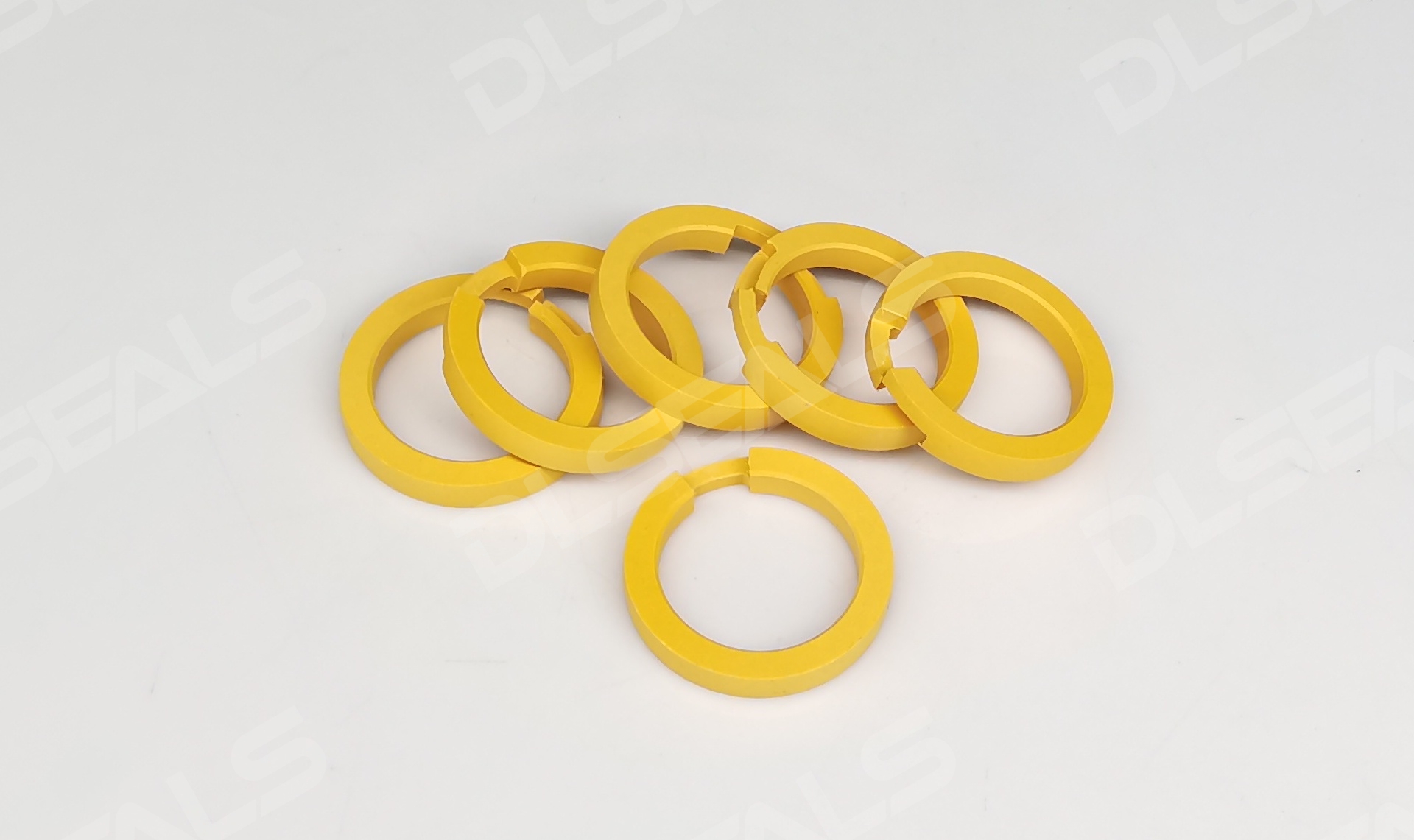
In modern turbocharged engines, sealing rings constitute the ultimate defense between extreme combustion energy and mechanical integrity. Positioned at critical interfaces of the turbine shaft, these miniature components withstand:
- 950°C exhaust gases
- 180,000 rpm centrifugal forces
- **>3 bar pulsating pressure differentials**
Failure induces oil coking, boost leaks, or catastrophic bearing seizure – making sealing innovation paramount.
I. The Sealing Trinity: Functions & Failure Modes
Triune Functions and Failure Boundaries of Turbo Seals
| Function | Location | Failure Consequence |
|---|---|---|
| Oil Containment | Compressor/Turbine shaft journals | Oil ingress into exhaust → blue smoke emission, catalytic converter poisoning |
| Boost Pressure Lock | Compressor backplate | Power loss, delayed turbo spool response (e.g., >15% boost drop) |
| Exhaust Gas Isolation | Turbine housing interface | Hot gas leakage → bearing oil carbonization |
II. Material Evolution: From Graphite to Advanced FKM/PTFE Hybrids
Material Evolution: Triumph of High-Temperature Polymers
- Limitations of Traditional Materials
- Graphite-coated steel rings: Crack at >750°C due to CTE mismatch
- Silicone rubber (VMQ): Degrades in direct exhaust path (<500h service life at >250°C)
- Fluoroelastomer Breakthroughs
- High-Temp FKM (e.g., DuPont™ Viton® Extreme™): Withstands 300°C peak temperatures, superior oil resistance.
- PTFE Composites: Carbon fiber/graphite fillers → 40% lower friction coefficient, enhanced wear resistance (e.g., Saint-Gobain NORGLIDE® HP).
- Multi-layer seal rings: Steel skeleton + FKM sealing lip + PTFE friction surface → unifies dynamic and static sealing.
III. Design Challenges: Dancing Between Rotation and Stasis
Design Challenges: Precision Balance at Dynamic-Static Interfaces
- Thermal Expansion Labyrinth: Differential expansion between turbine shaft (steel) and housing (cast iron) up to 0.3mm → necessitates radial compliance.
- Micron-Level Clearance Control: Ideal oil film thickness 3-8μm. Insufficient film causes dry friction; excessive film induces oil leakage.
- Reverse Pressure Trap: Inadequate compressor backpressure at low speeds → requires spring-assisted lip expansion (e.g., Wave-Spring design).
IV. Future Frontiers: Smart Seals & Material Revolution
Future Frontiers: Integrated Sensing & Ultra-High-Temp Materials
- Embedded Sensors: RFID tags monitoring seal temperature/wear → enabling predictive maintenance.
- Ceramic Matrix Composites (CMC): Endure >1000°C (e.g., SiC/SiC), applied in next-gen lean-burn turbos.
- Active Air Film Seals: Utilizing boost pressure to form dynamic gas barriers → near-zero friction (e.g., BorgWarner eTurbo™ concept).
Post time: Jun-19-2025

